> For the complete documentation index, see [llms.txt](https://tk233.gitbook.io/notes/llms.txt). Markdown versions of documentation pages are available by appending `.md` to page URLs; this page is available as [Markdown](https://tk233.gitbook.io/notes/tools/windows/getting-started-with-xbee-zigbee.md).
# Getting Started with XBee (ZigBee)
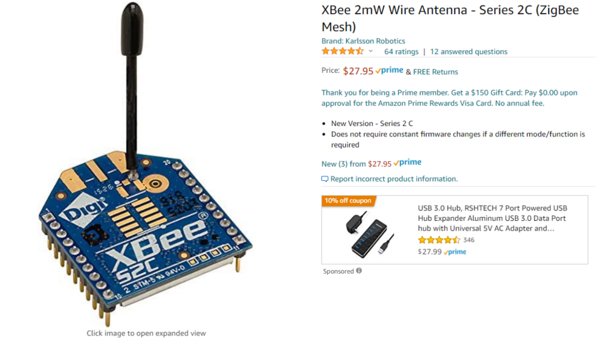
I’m using the XBee S2C module from Amazon:
## 1. Wiring
First, we need to wire up the XBee. Originally, I was going to use an Arduino UNO to do the USB-TTL conversion. However, I had no luck with it. Not sure about the reason. Maybe because I’m using a non-official clone, which has a different onboard USB-TTL chip?
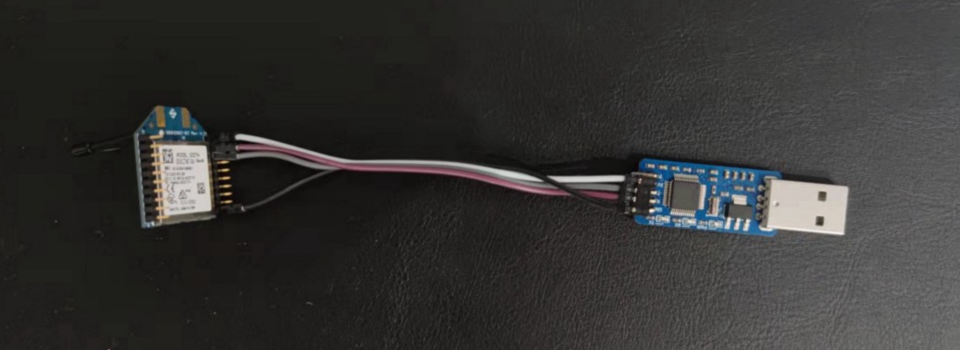
Then I realized that I can just use a plain USB-TTL converter to establish the link between the XBee module with the computer. I’m using the Rath RA-LINK module, originally designed for the GD32VF series MCU. We will just use the serial converter function of this debugger.
An additional benefit of this setup is that both end are using the 2.0mm pitch Dupont connector. (Viva la metric unit!)
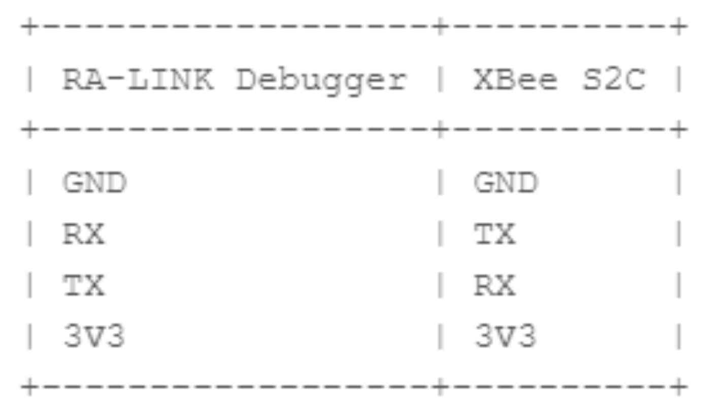
Here is the wiring diagram:
## 2. Download XCTU
Download XCTU from [here](https://hub.digi.com/support/products/xctu/?path=/support/asset/xctu-v-659-windows-x86x64/).
Insert the USB debugger into the computer and click this button.
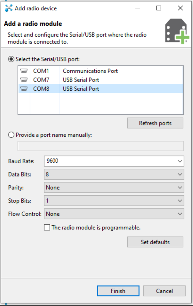
In the pop-up menu, we will select the corresponding COM port.
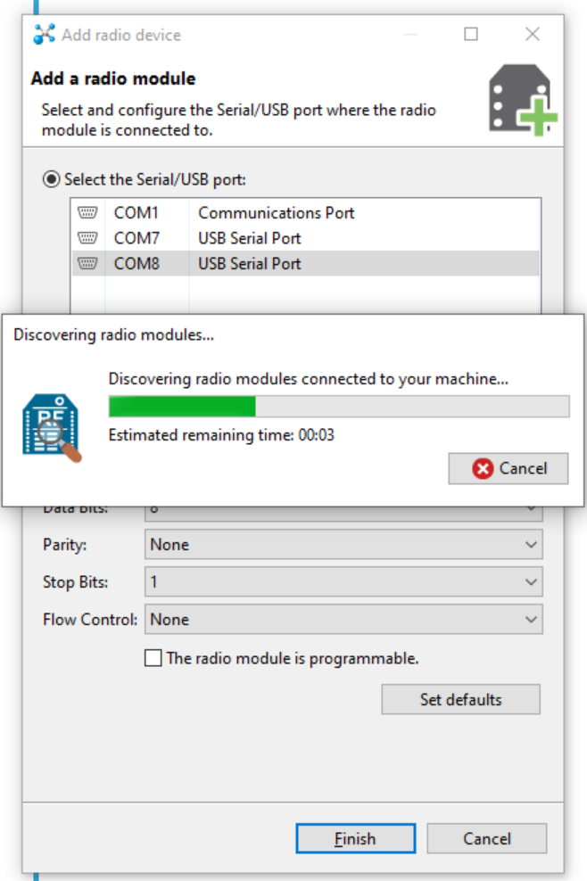
It will automatically search for the device.
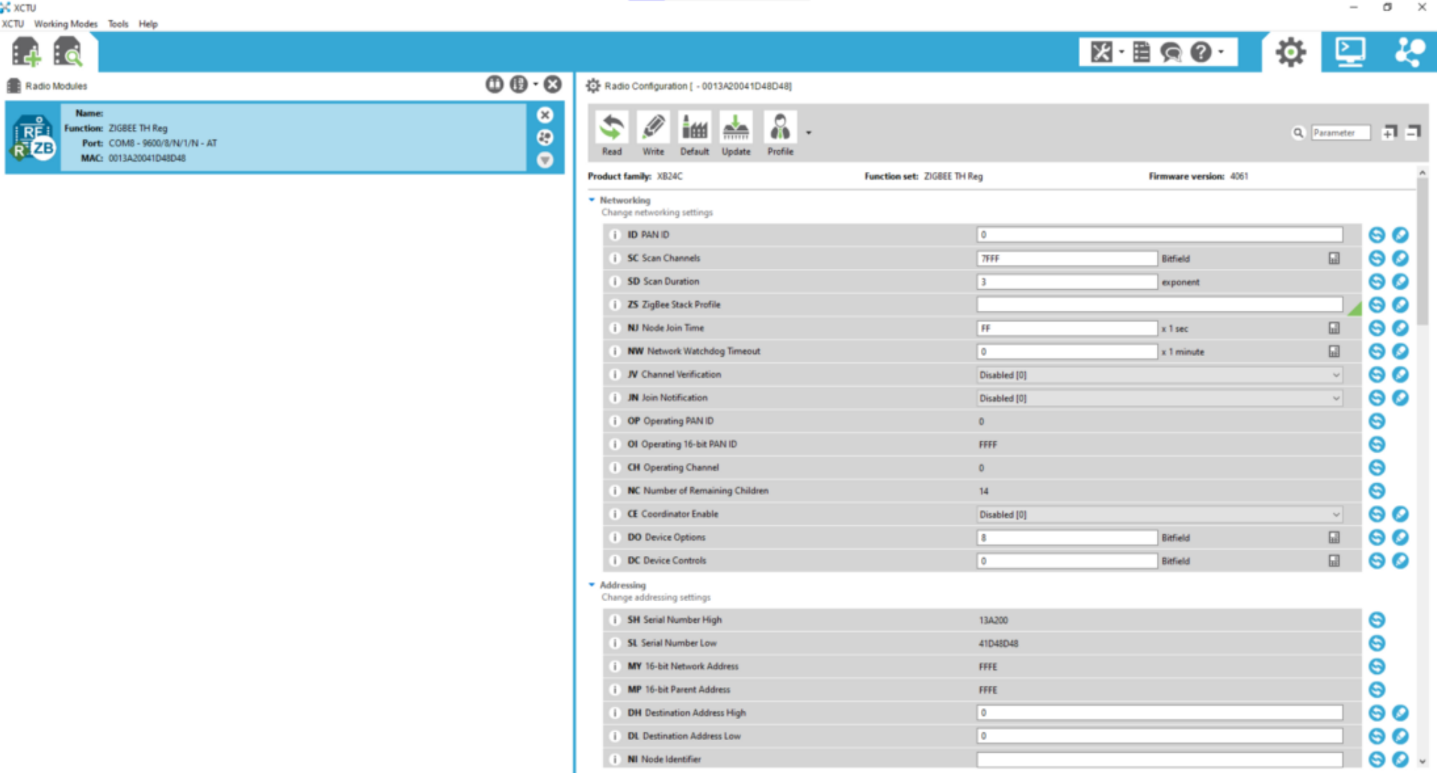
And then display its settings
We will make this first device the station (coordinator), and thus we modify the following fields:
**ID** (Pan ID): 2333
**CE** (Coordinator Enable): Enabled \[1]
**DL** (Destination Address Low): FFFF
**NI** (Node Identifier): XBee-Station
**BD** (Baud Rate): 115200 \[7]
And update the configuration by clicking this button
Then the station node is configured successfully.
Next, we perform the same thing for the car node, but this time with the following settings:
**ID** (Pan ID): 2333
**JV** (Channel Verification): Enabled \[1]
**DL** (Destination Address Low): 0
**NI** (Node Identifier): XBee-Car
**BD** (Baud Rate): 115200 \[7]
Now we are ready to test the connections.
Press this button to switch to the terminal window
And click this button to open the serial port
Now when we type in one terminal, we can see the contents appear in another terminal, indicating that the connection is established
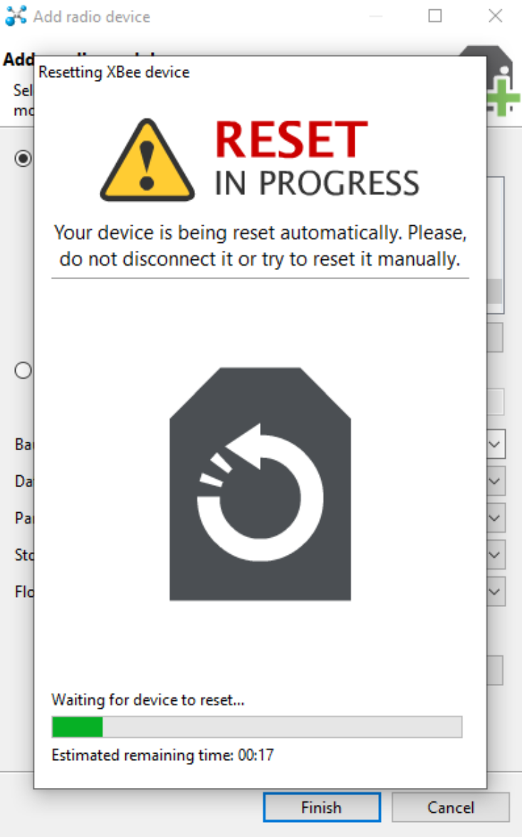
P.S. if the wrong configuration is entered in XBee parameters, XCTU will try to perform a revert on the chip
## 3. STM32 Code
Because XBee uses simple TX and RX to transmit data, we can simply program the STM32 to transmit and listen to data on the [USART port](/notes/stm32/connectivity/uart.md).
\\
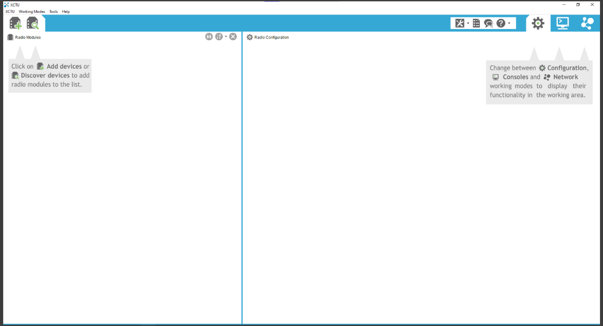
 In the pop-up menu, we will select the corresponding COM port.
 Then the station node is configured successfully.
Next, we perform the same thing for the car node, but this time with the following settings:
**ID** (Pan ID): 2333
**JV** (Channel Verification): Enabled \[1]
**DL** (Destination Address Low): 0
**NI** (Node Identifier): XBee-Car
**BD** (Baud Rate): 115200 \[7]
Now we are ready to test the connections.
Press this button to switch to the terminal window
Then the station node is configured successfully.
Next, we perform the same thing for the car node, but this time with the following settings:
**ID** (Pan ID): 2333
**JV** (Channel Verification): Enabled \[1]
**DL** (Destination Address Low): 0
**NI** (Node Identifier): XBee-Car
**BD** (Baud Rate): 115200 \[7]
Now we are ready to test the connections.
Press this button to switch to the terminal window
 And click this button to open the serial port
 Now when we type in one terminal, we can see the contents appear in another terminal, indicating that the connection is established